It’s been roughly 15 years since I made an entity–relationship model, so it is with great surprise that I sat in a meeting the other day and thought to myself “This project needs an ER model before we can do anything else.” I almost asked out loud, “WHO SAID THAT!?” But once I got over the initial shock I realized that my subconscious isn’t completely full of crap (this time).
But let’s back up. I’m working on a project to combine a variety of different back-end services into a single product. As we were talking about it and the discussion shifted to design, I realized that before we could create user journeys and get started on the interaction design we first needed to understand the relationships between the different entities in those services. I worried that without that model, we’d get ourselves tangled up really quickly.
So I brushed up on my theory1 and got to it. First, the obligatory definition:
[An] entity–relationship model (ER model) is a data model for describing the data or information aspects of a business domain or its process requirements, in an abstract way that lends itself to ultimately being implemented in a database such as a relational database. The main components of ER models are entities (things) and the relationships that can exist among them.
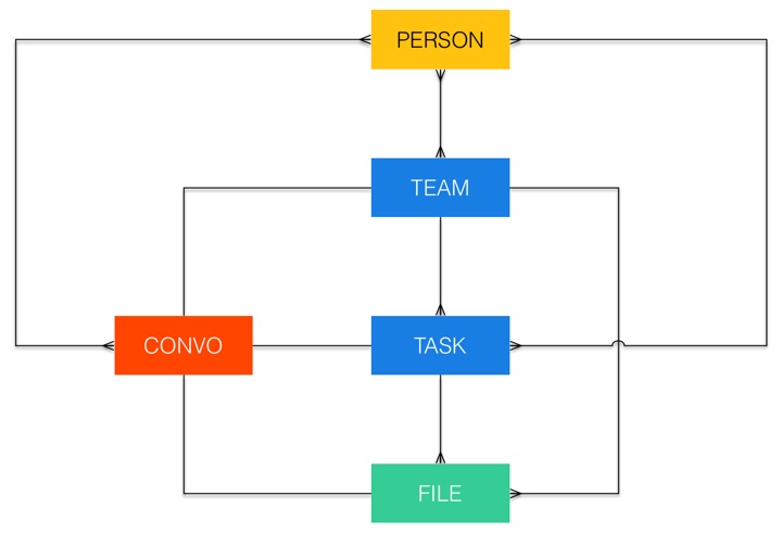
This is a tool that’s primarily used as the first step in relational database design. But I found it really useful for us to define the constraints within which we could create user flows. Let me explain with an example. Here’s a simplified version of the ER model we came up with for this project (using Crow’s foot notation):

Each color represents a different back-end service. Here’s a subset of what the diagram tells us:
- A team can have multiple tasks, but each task can only be assigned to one team.
- A task can have multiple files associated with it, but each file can belong to only one task (or team).
- A person can be part of multiple teams, and a team is made of multiple people.
- There is a 1:1 relationship between teams, tasks, files, and the conversations about those entities.
- Outside of those relationships, a person can be part of multiple conversations, and a conversation can consist of multiple people.
If all this sounds a little bit boring, I hear you, but here’s the power of this diagram: it ensures that whatever UI we come up with serves the underlying entity relationships, and not the other way around. This is huge. For example, if we started with the UI we might say that users can attach files to a task or project within the product’s main interface. But since a 1:1 relationship exists between Conversation and File, it means we can also attach a file to a task by dropping it into the Conversation view of that task. The relationships help us to come up with the most useful and robust UI.
What essentially happens if you start UI design with an ER model is that you create the boundaries of what’s “allowed” in the UI. It pushes you to think up useful ideas without the danger of coming up with something that wouldn’t work in the final implementation.
I don’t think ER models should be the starting point of every project. But in certain specific cases where many disparate products or services need to come together it’s proved to be really useful.
And now, on to journey mapping…
-
Ok fine, I read the Wikipedia article. ↩